Constructing a Cartesian mesh
The cart_mesh program is used to generate Cartesian meshes for the cgcam code. Cart_mesh reads inputs from file cart_mesh.inp, using a strategy very similar to that which is used to read inputs for the main cgcam code (see section User Input Variables). All possible inputs for cart_mesh.inp are listed below:
| Nx: | Number of points in x. |
|---|---|
| Ny: | Number of points in y. |
| Nz: | Number of points in z. |
| x0: | Minimum value of the x coordinate. |
| x1: | Maximum value of the x coordinate. |
| xL: | Box size in the x-direction. |
| y0: | Minimum value of the y coordinate. |
| y1: | Maximum value of the y coordinate. |
| yL: | Box size in the y-direction. |
| z0: | Minimum value of the z coordinate. |
| z1: | Maximum value of the z coordinate. |
| zL: | Box size in the z-direction. |
| dx0: | x mesh spacing for the uniform mesh region. |
| dy0: | y mesh spacing for the uniform mesh region. |
| dz0: | z mesh spacing for the uniform mesh region. |
| dz1: | Mesh spacing at the surface when i_type_z=2. |
| x_trans1: | x location for the start of the uniform mesh region. |
| x_trans2: | x location for the end of the uniform mesh region. |
| y_trans1: | y location for the start of the uniform mesh region. |
| y_trans2: | y location for the end of the uniform mesh region. |
| z_trans1: | z location for the start of the uniform mesh region. |
| z_trans2: | z location for the end of the uniform mesh region. |
| rot: | Rotation angle about the y-axis. |
| flare: | Tangent of the flare angle when i_grid=11. |
| i_grid: | Grid type: 0-Cartesian grid written as a full 3D grid file, 1-Cartesian grid written as a compact file, 11-Cartesian grid with a flared region near the top boundary. Default is 1. |
| i_type_z: | Vertical mesh stretching control: 0-attempt to match the stretching rates in the two stretched regions, 1-attempt to match the mesh spacings at the ends of the two stretched regions, 2-stretch from dz1 at the surface to dz0 at z_trans1. Default is 1. |
Of these possible inputs, only the number of mesh points (Nx, Ny, and Nz) are strictly required. It is also required to specify the computational box dimensions in some fashion. This can be done by specifying the box dimension itself (e.g. xL in which case x will range between -0.5*xL to 0.5xL) or by specifying the coordinate ranges (e.g. x0=1.0, x1=11.0, or x0=1.0, xL=10.0, or x1=11.0, xL=10.0). If only the number of mesh points and the box dimensions are given for a particular direction, cart_mesh will assume a uniform mesh spacing in that direction. For example, the minimal input file
Nx            10          Number of points in x
Ny             1          Number of points in y
Nz             5          Number of points in z
xL          100.0         Box size in the x-direction
yL            1.0         Box size in the y-direction
z0            0.0         Minimum value of the z coordinate
z1           30.0         Maximum value of the z coordinate
generates the mesh below
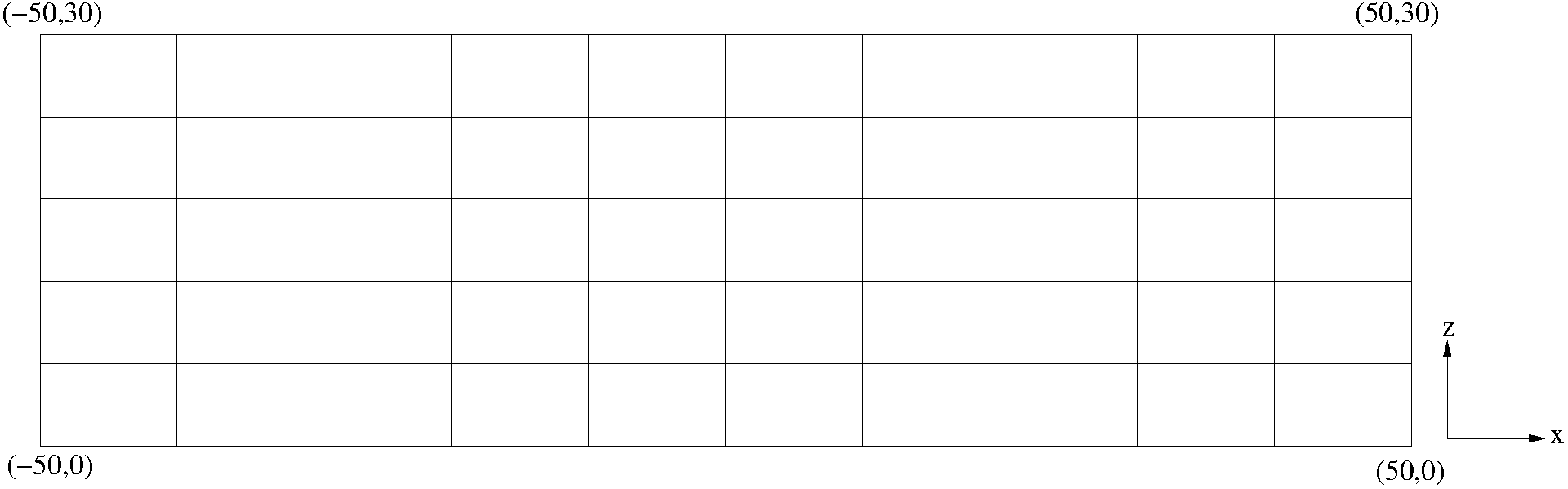
Fig. 1 Uniform mesh layout in the x-z plane.
Note that Ny=1 is specified in the input file, which results in a 2D mesh. While this was done for illustrative purposes, cart_mesh will generally be used to generate 3D meshes. The remaining examples in this section will also be 2D, but all of the concepts covered extend to 3D.
Often it is desirable to cluster mesh points in a portion of the domain where smaller-scale structures will develop. The current strategy is to use a uniform fine mesh spacing in the refined zone, and then stretch the mesh towards the boundaries (the procedure will be made more clear in the examples below). In order to obtain a refined zone, it is necessary to specify the limits of the uniform mesh region, as well as the mesh spacing there (e.g. x_trans1, x_trans2, dx0). For example, the input file
Nx          60        Number of points in x
Ny          1         Number of points in y
Nz          60        Number of points in z
x0         -1.0       Minimum x coordinate
x1          1.0       Maximum x coordinate
yL          0.1       Spanwise box size
z0          0.0       Altitude for bottom of domain
z1          1.0       Altitude for top of domain
dx0         0.015     x mesh spacing for uniform section
x_trans1   -0.2       x-coordinate for start of uniform section
x_trans2    0.3       x-coordinate for end   of uniform section
generates the mesh below
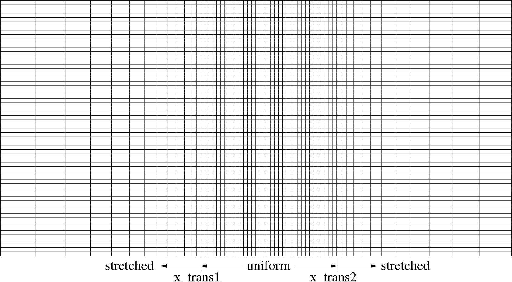
Fig. 2 Mesh with a refined zone in the x-direction.
Similar refinements can be made in the y and z directions by specifying the optional input parameters y_trans1, y_trans2, dy0, z_trans1, z_trans2, and dz0. Additional options are available for the z direction only in order to provide more on the mesh stretching strategy and to accommodate terrain features that may exist at the lower boundary. In the x and y directions, cart_mesh will attempt to make the largest mesh cells in the two stretched regions (at the two ends of the domain) equal in size. This is also the default behavior in the z direction, but it not produce the desired effect. For example, it might make sense to have a reasonably fine vertical mesh spacing near the lower boundary, but a much larger spacing near the upper boundary. The optional input i_type_z=0 will change the behavior so that the mesh stretching rates are equal in the two stretched zones. By placing the refined mesh zone appropriately, it is then possible to achieve the desired inequality between the vertical mesh spacings at the lower and upper boundaries. An example of this feature is shown below
Nx          60        Number of points in x
Ny          1         Number of points in y
Nz          40        Number of points in z
x0         -1.0       Minimum x coordinate
x1          1.0       Maximum x coordinate
yL          0.1       Spanwise box size
z0          0.0       Altitude for bottom of domain
z1          1.0       Altitude for top of domain
dx0         0.015     x mesh spacing for uniform section
x_trans1   -0.2       x-coordinate for start of uniform section
x_trans2    0.3       x-coordinate for end   of uniform section
dz0         0.015     z mesh spacing for uniform section
z_trans1    0.2       z-coordinate for start of uniform section
z_trans2    0.4       z-coordinate for end   of uniform section
i_type_z    0         0-match sf, 1-match dz, 2-stretch from surface
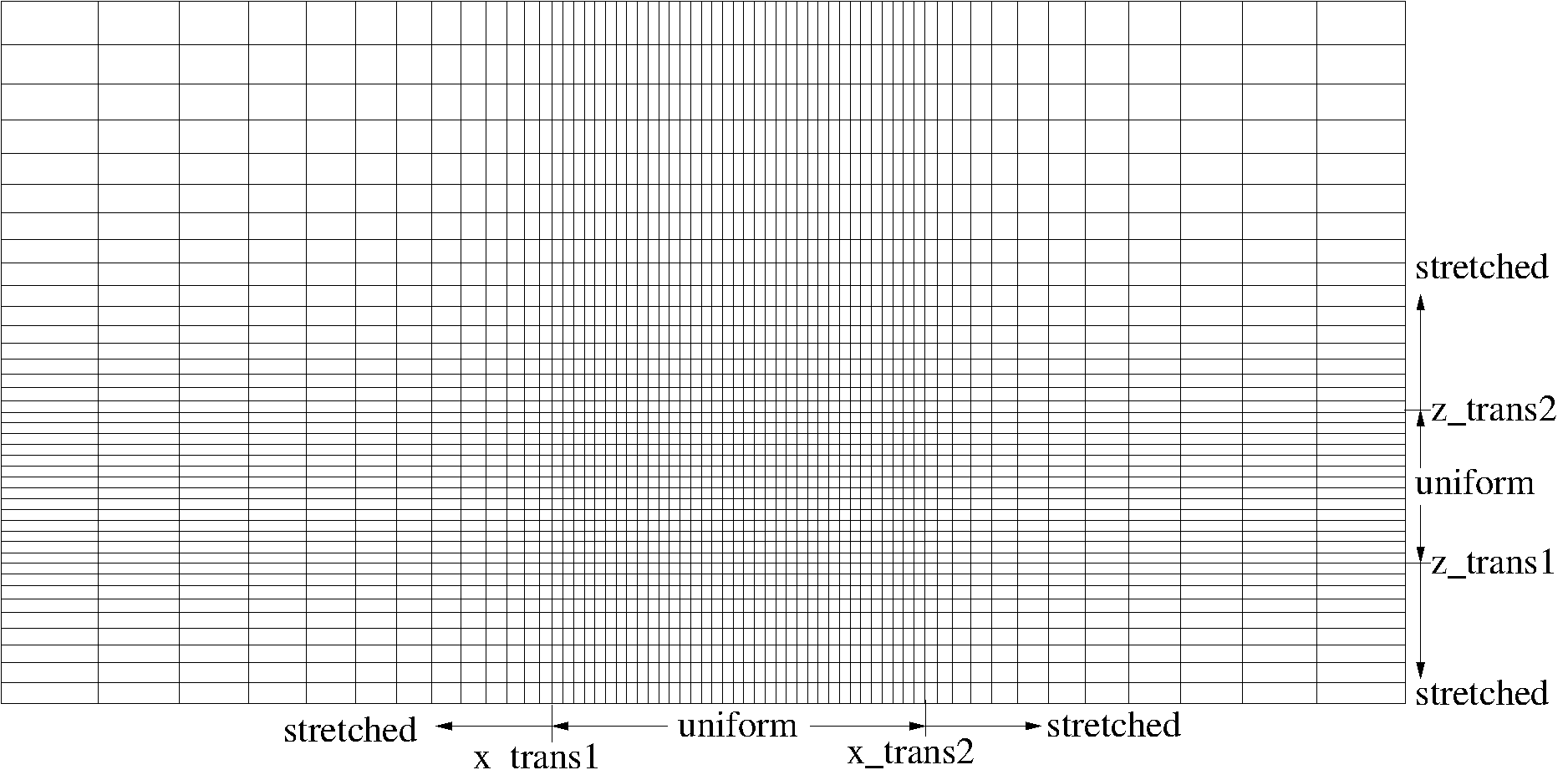
Fig. 3 Mesh with a refined zones in both the x and z directions. i_type_z=0 is specified in order to allow for unequal vertical mesh spacings at the lower and upper boundaries.
A second option, i_type_z=2 is available in order to allow for very fine vertical spacing near the surface (specified by optional input dz1), followed by a stretching zone where the spacings increase in the vertical until meeting the uniform mesh zone with spacing dz1 at z_trans1. This feature is illustrated below
Nx          60        Number of points in x
Ny          1         Number of points in y
Nz          50        Number of points in z
x0         -1.0       Minimum x coordinate
x1          1.0       Maximum x coordinate
yL          0.1       Spanwise box size
z0          0.0       Altitude for bottom of domain
z1          1.0       Altitude for top of domain
dx0         0.015     x mesh spacing for uniform section
x_trans1   -0.2       x-coordinate for start of uniform section
x_trans2    0.3       x-coordinate for end   of uniform section
dz0         0.015     z mesh spacing for uniform section
z_trans1    0.2       z-coordinate for start of uniform section
z_trans2    0.4       z-coordinate for end   of uniform section
i_type_z    2         0-match sf, 1-match dz, 2-stretch from surface
dz1         0.008     z mesh spacing at the lower boundary
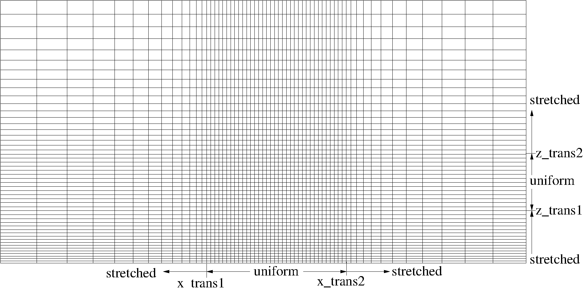
Fig. 4 Mesh with a refined zones in both the x and z directions. i_type_z=2 is specified in order to produce fine vertical spacing dz1 at the lower boundary.
The numerical algorithm used in cgcam is rather sensitive to mesh smoothness and oscillations will often appear in the solution variables if the mesh is stretched too aggressively. As a general rule, the mesh stretching rates should be limited to a maximum of about 2%. In order to assist the user in this regard, the cart mesh prints the computed stretching rates to the screen as it runs. A sample output is shown below.
x-direction:
 n_stretch1 =   39      n_uniform =   37      n_stretch2 =   32
 sf1 = 1.01622      sf2 = 1.01932
 Delta_end1 =  2.7396E-02      Delta_end2 =  2.6906E-02

y-direction:
 n_stretch1 =    0      n_uniform =    1      n_stretch2 =    0
 sf1 = 1.00000      sf2 = 1.00000
 Delta_end1 =  1.0000E-01      Delta_end2 =  1.0000E-01

z-direction:
 n_stretch1 =   12      n_uniform =   13      n_stretch2 =   29
 sf1 = 1.01443      sf2 = 1.02035
 Delta_end1 =  1.8011E-02      Delta_end2 =  2.7047E-02
The stretching rates are reported as sf1 and sf2 for each direction and are quoted as the ratio of two adjacent mesh spacings. Thus a number like 1.0195 indicates a stretching rate of 1.95%. Note that the stretching rates are generally unequal in the two stretched regions for each direction. It is thus necessary to scan for both values and then increase the number of mesh points as required in order to lower the larger of the two to about 1.02.
Note that the stretching rates for the examples in this section grossly violate the 2% rule. This was done for illustrative purposes only as it is difficult for the human eye to register stretching rates as low as 2%.
the cgcam code is often used for atmospheric simulations where the upper boundary is placed at an altitude of 200 km or higher. Fine mesh spacings near the upper boundary for these cases can result in a severe time step restriction due to the explicit time advancement scheme in connection with the large values of kinematic viscosity found at high altitudes. Mesh stretching in the vertical does not help too much in these cases since the time step is still limited by diffusion across the fine mesh dimensions in the horizontal directions. One strategy aimed at combating this problem is to bend the mesh lines in the upper portion of the domain in order to increase their horizontal spacings there. Although this procedure moves the mesh topology from strict Cartesian to distorted Cartesian, it can nonetheless be done within cart_mesh. In order to use this feature, it is necessary to supply the optional input flare=tan(flare angle). This feature is illustrated in the example below.
Nx          60        Number of points in x
Ny          1         Number of points in y
Nz          40        Number of points in z
x0         -1.0       Minimum x coordinate
x1          1.0       Maximum x coordinate
yL          0.1       Spanwise box size
z0          0.0       Altitude for bottom of domain
z1          1.0       Altitude for top of domain
dx0         0.015     x mesh spacing for uniform section
x_trans1   -0.2       x-coordinate for start of uniform section
x_trans2    0.3       x-coordinate for end   of uniform section
dz0         0.015     z mesh spacing for uniform section
z_trans1    0.3       z-coordinate for start of uniform section
z_trans2    0.6       z-coordinate for end   of uniform section
flare       0.2       Tangent of the flare angle
i_type_x    0         0-match sf, 1-match dx
i_type_z    0         0-match sf, 1-match dz, 2-stretch from surface
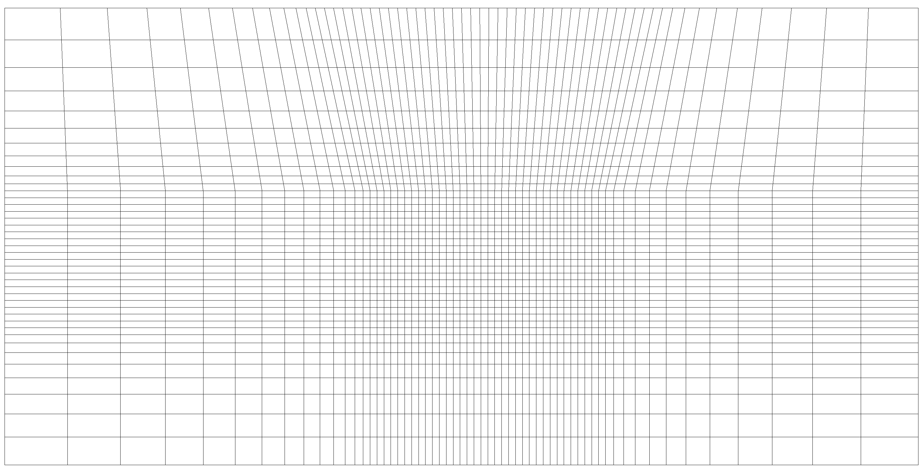
Fig. 5 Mesh with a flared region near the upper boundary.
Advanced Features
In September of 2025 several additional features were added to the cart_mesh program in order to increase its functionality. The new features include
- It is now possible to specify two distinct refined zones in each coordinate direction.
- You can now specify the maximum stretching rate in each coordinate direction instead of the number of mesh points. Cart_mesh will determine the number of mesh points such that the stretching rate remains below the specified value.
- Since the specified stretching rate method can result in inconvenient mesh point numbers, it is now possible to also specify a decomposition factor in each direction so that the number of mesh points is divisible by the specified factor.
- If desired, a header record can be prepended to the grid file in order to keep track of the number of mesh points.
- Rather general mesh layouts can now be created by specifying grid spacings, stretching type (expanding, uniform, contracting) in a total of 6 mesh zones.
The new features require several additional inputs
| x_trans3: | x location for the start of the second uniform mesh region. |
|---|---|
| x_trans4: | x location for the end of the second uniform mesh region. |
| y_trans3: | y location for the start of the second uniform mesh region. |
| y_trans4: | y location for the end of the second uniform mesh region. |
| z_trans3: | z location for the start of the second uniform mesh region. |
| z_trans4: | z location for the end of the second uniform mesh region. |
| sfx_max: | Maximum allowed stretching rate in the x-direction (default 1.02). |
| sfy_max: | Maximum allowed stretching rate in the y-direction (default 1.02). |
| sfz_max: | Maximum allowed stretching rate in the z-direction (default 1.02). |
| i_fac_x: | If Nx is computed, it will be divisible by i_fac_x. |
| i_fac_y: | If Ny is computed, it will be divisible by i_fac_y. |
| i_fac_z: | If Nz is computed, it will be divisible by i_fac_z. |
| dx1-dx7: | Mesh spacings in x at the boundaries of up to 6 mesh zones |
| dy1-dy7: | Mesh spacings in y at the boundaries of up to 6 mesh zones |
| dz1-dz7: | Mesh spacings in z at the boundaries of up to 6 mesh zones |
| i_sdx1-isd_x6: | Mesh stretching type in up to 6 mesh zones in x. |
| i_sdy1-isd_y6: | Mesh stretching type in up to 6 mesh zones in y. |
| i_sdz1-isd_z6: | Mesh stretching type in up to 6 mesh zones in z. |
| i_header: | Header control: 0-no header 1-write header |
Several of the new inputs are illustrated in the following sketch which shows the layout for a grid point distribution in the x-direction having two refined zones.
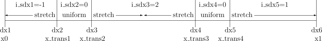
Fig. 6 Input parameters for a grid point distribution having two refined zones.
The boundaries of the uniform spacing refined zones are given by x_trans1, x_trans2 and xtrans_3, x_trans4. Although they are listed in the figure, non-zero mesh spacings values at the ends of the domain (dx1 and dx6) should not be specified since they will be determined during the solution process (values of 0 are acceptable, but not required). The parameters (i_sdx1-i_sdx5) specify the stretching direction, with -1 meaning that the mesh is compressed in the increasing index direction, 0 is uniform, 1 is expanding, and 2 is stretching away from either zone boundary with the coarsest spacing in the center. Although you could specify all of the dx and i_sdx values, cart_mesh will make a few assumptions to fill in the missing values when it sees that you are requesting a grid point distribution with two refined zones. More specifically, it is only necessary to specify x_trans1-x_trans4, dx2, and dx4. Cart_mesh will input the stretching direction parameters for you and will set dx1=0, dx3=dx2, dx5=dx4, and dx6=0. The maximum stretching factor will also default to 1.02, so it is not necessary to input this parameter unless more gradual stretching is desired.
Perhaps the best way to illustrate the new features is by example. The input file below will build a mesh that has two refined zones in x and y and a single refined zone in z:
Nz          240          Number of points in z
x0         -600.0e3      Minimum x coordinate
x1          600.0e3      Maximum x coordinate
y0         -600.0e3      Minimum y coordinate
y1          600.0e3      Maximum y coordinate
z0            0          Altitude for bottom of domain
z1          128.0e3      Altitude for top of domain
x_trans1    -85.0e3      x-coordinate for start of uniform section 1
x_trans2     85.0e3      x-coordinate for end   of uniform section 1
x_trans3    270.0e3      x-coordinate for end   of uniform section 2
x_trans4    310.0e3      x-coordinate for end   of uniform section 2
dx2           5.0e2      x mesh spacing for uniform section
dx4           8.0e2      x mesh spacing for uniform section
i_fac_x      10          Decomposition factor in x
y_trans1   -440.0e3      y-coordinate for start of uniform section 1
y_trans2   -400.0e3      y-coordinate for end   of uniform section 1
y_trans3    -85.0e3      y-coordinate for end   of uniform section 2
y_trans4     85.0e3      y-coordinate for end   of uniform section 2
dy2           8.0e2      y mesh spacing for uniform section
dy4           5.0e2      y mesh spacing for uniform section
i_fac_y      12          Decomposition factor in y
z_trans1      0.0e3      z-coordinate for start of uniform section 1
z_trans2    102.0e3      z-coordinate for end   of uniform section 1
dz0           5.0e2      z mesh spacing for uniform section
i_type_z      0          0-match sf, 1-match dz, 2-stretch from surface
Cart mesh requires that you use the maximum stretching rate method when two refined zones are included, and thus the Nx and Ny inputs are absent. The z-direction, on the other hand, uses the original method where Nz is specified. Per the discussion above, we only specify the transition points and the mesh spacings in the two refined zones. We also use the i_fac_x and i_fac_y inputs to produce Nx and Ny values that factor nicely. While the z-direction uses the original strategy, it sets z_trans1=z0, which effectively eliminates the first stretched region, resulting in a two-zone grid point distribution (a uniform section, followed by stretching to the upper boundary). Using the new strategy, the z grid point distribution could be specified alternatively by the following block of inputs, which may be more clear.
z_trans1    102.0e3      z-coordinate for end of uniform section 1
dz1           5.0e2      z mesh spacing at the lower boundary
i_sdz1        0          Stretching type for grid zone 1
i_sdz2        1          Stretching type for grid zone 2
i_fac_z      12          Decomposition factor in z
The resulting mesh in the xy plane is shown below.
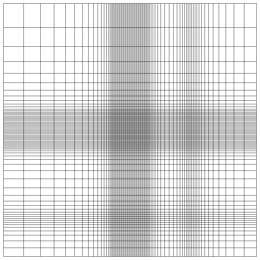
Fig. 7 Mesh with two refined zones in the xy plane. Only every 10th grid line is shown in x and every 12th in y for clarity.