Constructing a Terrain Mesh
The terrain_mesh program is used to generate a grid.dat file containing the information necessary for cgcam to construct a 3D mesh conforming to terrain at the lower surface. The resulting 3D mesh maintains Cartesian structure in the \(xy\) plane but deforms the top and bottom faces of cells in order to match the terrain. Due to this structure, the cart_mesh program is called internally by terrain_mesh in order to set up the underlying Cartesian grid. Thus it is necessary to provide the file cart_mesh.inp as described in Constructing a Cartesian mesh. It is also necessary to supply the file terrain_mesh.inp in order to specify the remaining parameters necessary to define the terrain grid. The structure of the terrain_mesh.inp file is very similar to that of file input.dat, which is described in Section User Input Variables All possible inputs for terrain_mesh.inp are listed below:
| lat_ref: | Latitude for reference point in domain. Required. |
|---|---|
| lon_ref: | Longitude for reference point in domain. Required. |
| lat_min_dat: | Specifies corner of the domain for custom data type. Required for custom data (i_dat_type=2). |
| lon_min_dat: | Specifies corner of the domain for custom data type. Required for custom data (i_dat_type=2). |
| delt_lan_dat: | Specifies size of the domain for custom data type. Required for custom data (i_dat_type=2). |
| delt_lat_dat: | Specifies size of the domain for custom data type. Required for custom data (i_dat_type=2). |
| Nx_dat: | Number of data points in x direction for custom data type. Required for custom data (i_dat_type=2). |
| Ny_dat: | Number of data points in y direction for custom data type Required for custom data (i_dat_type=2). |
| x_ref: | x coordinate of lat_ref, lon_ref. Default value 0.0. |
| y_ref: | y coordinate of lat_ref, lon_ref. Default value 0.0. |
| rot: | Rotation angle for x-y mesh relative to lines of constant latitude. Default value 0.0. |
| n_fit: | Interpolation order 1, 2 or 3. Default value 1. |
| i_dat_type: | Type of data files 0-GLOBE, 1-SRTM, 2-custom. Default value 1. |
| width_x: | Width of the terrain damping function in x. Default value 0.0. |
| width_y: | Width of the terrain damping function in y. Default value 0.0. |
| x_damp0: | Position of damping function at the left x boundary. Default value -1.0e+12. |
| x_damp1: | Position of damping function at the right x boundary. Default value 1.0e+12. |
| y_damp0: | Position of damping function at the bottom y boundary. Default value -1.0e+12. |
| y_damp1: | Position of damping function at the top y boundary. Default value 1.0e+12. |
| z_edge: | Altitude to set terrain around the damped edges. Default value 0.0. |
| i_rot_vtk: | 0-surface.vtk displayed in local (rotated coordinates) 1-surface.vtk displayed in global coordinates. Default value 0. |
Of these possible inputs, only the lat_ref and lon_ref strictly required.
The remaining inputs are optional and are assigned the default values listed
above if they are not contained in file terrain_mesh.inp. Three elevation
data bases are available and these are selected by the parameter i_dat_type.
The GLOBE and SRTM data sets are standardized open source products and these
will be discussed in more detail below. It is also possible to provide
terrain_mesh with custom elevation data that can come from any other source.
In this case it is necessary to provide the inputs lat_min_dat, lon_min_dat,
delt_lan_dat, delt_lat_dat, Nx_dat, and Ny_dat in order to fully specify the
elevation data file structure. By default terrain_mesh will look for
elevation data files in the directory where it is executed. It is also
possible to supply the path to the elevation files by placing the line
data_path path_to_elevation_data_files at the bottom of the
terrain_mesh.inp file. There must be a blank line between the inputs
discussed above and the data path. It is good practice to store all required
elevation data files in a separate location with plenty of storage for
convenience and to avoid multiple instances of the data files. An example of
a minimal terrain_mesh.inp file is shown below:
lat_ref 117.0  Latitude  for reference point in domain
lon_ref  40.0  Longitude for reference point in domain

data_path /your/path/to/elevation/data
Determining the Domain
First, the user should choose the latitude and longitude reference point for
the computational domain. It is useful to assign reference to a specific
physical location, such as an important landmark within the domain. Other
logical choices are the geometric center of the computational domain or the
centroid of a region of locally-refined mesh (as produced by the cart_mesh
program). Google Earth is a convenient tool to determine both the
coordinates of the reference point as well as the dimensions of the desired
computational domain. The draw line or shape options are useful for
drawing the footprint of the computational domain on the map and the
ruler feature is handy for generating distance information. The figure
below illustrates the use of Google Earth to rough out a computational
domain. Note that the computational domain has been rotated so that the
mountain range in this case is roughly aligned with one of the coordinate
directions. While not strictly necessary, doing this allows the mountain
range to be resolved efficiently with a compact region of mesh refinement.
The distance information (as measured in the rotated coordinate system)
will go into the cart_mesh.inp file as x0, x1, y0, y1 and the rotation
angle will enter the terrain_mesh.inp file as the input rot. The
convention is that a positive rot value rotates the domain clockwise.
Thus in the example below rot should be assigned a negative value.
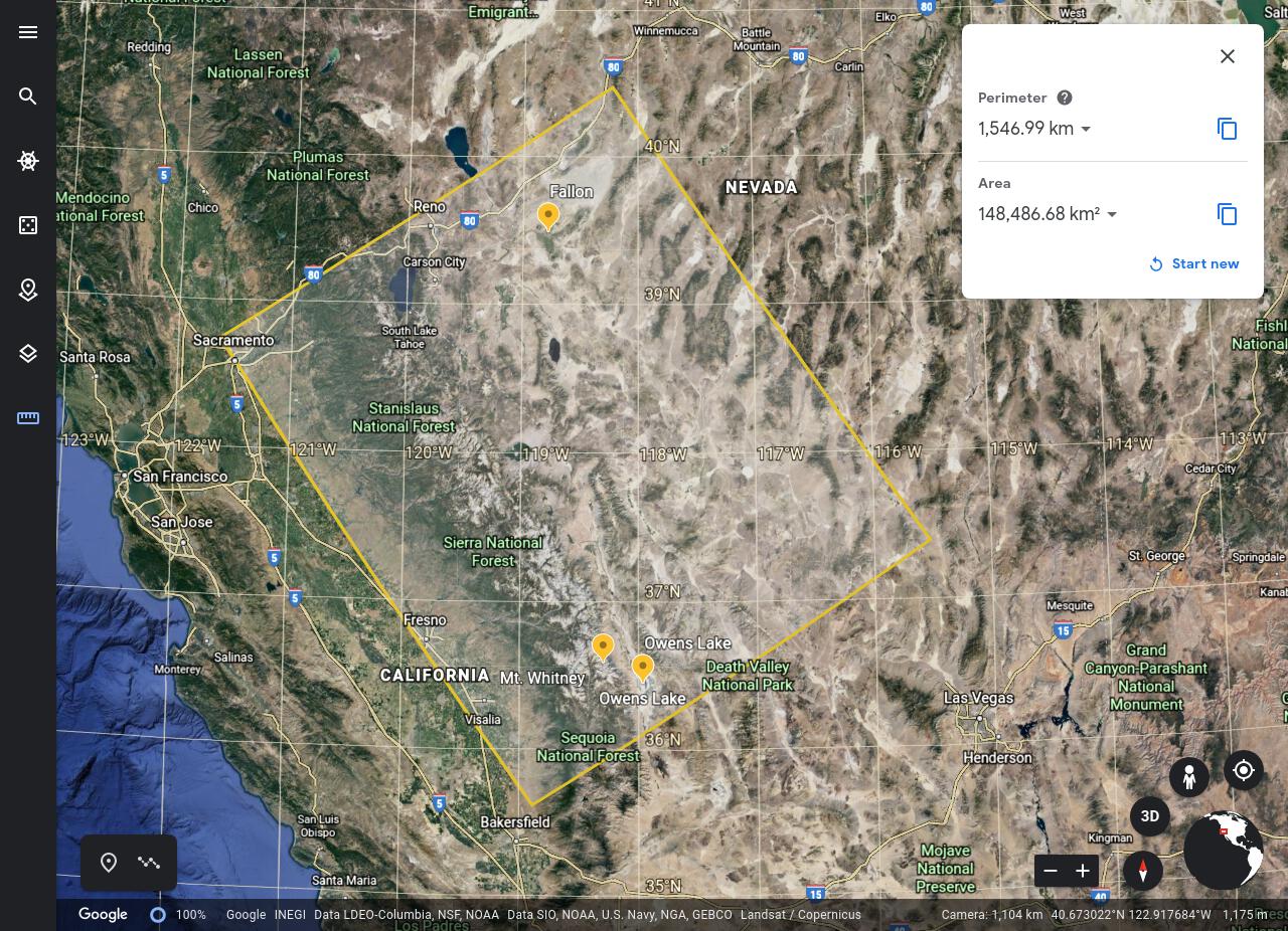
Fig. 6 Google Earth selection of the Sierra Nevada Mountains
By default, the origin of the Cartesian grid will be located at the the latitude, longitude reference point lat_ref,lon_ref, but this behavior can be overridden by supplying the optional inputs x_ref and y_ref. In either case it is important to that the x0, x1, y0, y1 values listed in the cart_mesh.inp file are consistent with the domain boundaries relative to the reference point.
The bounds for local mesh refinement in x and y can also be determined from the Google Earth image. These values will appear as inputs x_trans1, x_trans2, y_trans1, and y_trans2. The figure below shows a completed terrain grid (the thin white line) overlayed on a larger section of elevation data.
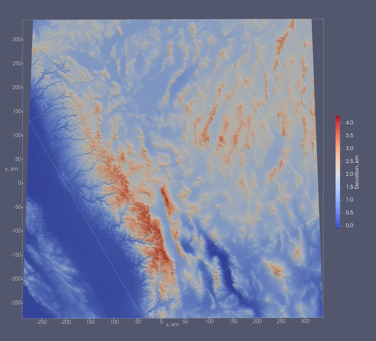
Fig. 7 Elevation Map over the Sierra Nevada Mountains Rotated -30°
Choosing an Elevation Data Set
Terrain_mesh supports two standard elevation data sets, the NOAA GLOBE 30 arc second (~930 m) data and the USGS SRTM 1 arc second (~31 m) data. While the resolution of the SRTM data is 30 times higher that that of the GLOBE data, it is only available from 60° north to 56° south. The GLOBE data, on the other hand, covers the entire earth. Due to the increased resolution, the SRTM data files are a factor of \(30^2=900\) times larger than GLOBE data files covering the same region. Thus the data overhead can be a concern for the SRTM data set, especially for large domains. In general the GLOBE data is better suited for large domains (~1000 km) having modest mesh spacing (500-1000 m), whereas the SRTM data is better suited for smaller domains (~200 km) having higher resolution (50-200 m).
Terrain_mesh also supports a custom data type where the user specifies the characteristics of the elevation data file. Each of the three data formats are discussed below.
Note that after specifying a data type, the terrain mesh program will indicate all required data files if they are not found in the data path.
Global Land One-kilometer Base Elevation (GLOBE)
As mentioned above, the NOAA GLOBE data set is the most complete data type of the three available since it covers the entire earth. In order to use it, one or more of the 16 elevation data tiles must be downloaded from
and stored locally on the computer where terrain_mesh is to be run. A map on the page referenced above can be used to identify the required tiles.
Note that the 30 arc second resolution gives a latitude data spacing of approximately 930 m. The spacing in the longitude direction depends on the latitude via 930*cos(latitude) m. At 45° latitude, the longitude spacing is about 660 m. Due to the sampling limits, the terrain will not be well resolved if the computational grid spacings are significantly finer than these values. Both second and third order interpolation schemes (n_fit=2, 3) are available and these can be used to at least produce smooth terrain from the under-sampled elevation data. Although the higher order interpolation schemes can also be used for coarse meshes (greater than 1000 m spacing) the end result will be nearly identical to that produced with linear interpolation (n_fit=1)
A sample input for the GLOBE data over the Rocky Mountains in Colorado:
lat_ref      40.0000   Latitude  for point in domain
lon_ref     -105.875   Longitude for point in domain
i_data_type     0      GLOBE data
n_fit           3      Interpolation order 1, 2 or 3.

data_path /your/path/to/GLOBE/data
After interpolation on a uniform 250 m grid (See section Constructing a Cartesian mesh), a section of the surface is shown below:
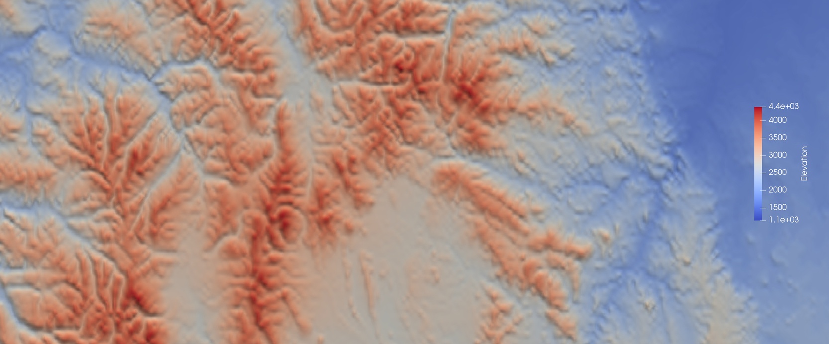
Fig. 8 Rocky Mountains Elevation Map Globe data set
Shuttle Radar Topography Mission (SRTM)
The SRTM 1-arc-second data set is sampled 30 times finer than the GLOBE data, but its coverage is limited to the latitude range 60° North to 56° South. In order to account for the cos(latitude) factor on the longitude data spacing, the sampling longitude direction is increased to 2 arc seconds for latitudes greater than +/- 50° degrees. At the equator, the longitude spacing is about 31 m. At 49.9 degrees it reduces to about 20 m, and then jumps up to about 40 m as the 50° line is crossed. It then decreases gradually back to 31 m at 60° latitude. Since the SRTM data is so finely sampled, the linear interpolation scheme should be adequate for the vast majority of cases.
To download the SRTM data files, create and account on the USGS EarthExplorer available at
After logging in to the site, the easiest method of finding the required data files is to simply draw the domain (in a manner similar to the Google Earth description given above) and then hit the search button. For more accurate results it is possible to supply the latitude longitude coordinates of the corner points of the domain. The terrain_mesh program will print these coordinates to the screen when run. It will also print out a list of missing elevation data files. Thus the program can be run before the elevation data files have been downloaded and the output information can then be used to identify and verify the required data files.
After finding the appropriate domain, use the following steps:
- Click 'Data Sets'
- Search for 'SRTM 1 Arc-Second Global'
- Click 'Results'
- Download the '.BIL' file type (Either one at a time or install the Bulk Downloader in checkout)
For a complete tutorial of the EarthExplorer the USGS help documentation is available. EarthExpolorer Tutorial
A sample surface for the SRTM data over the Rocky Mountains in Colorado linearly interpolated on a uniform 250 m grid is shown below.
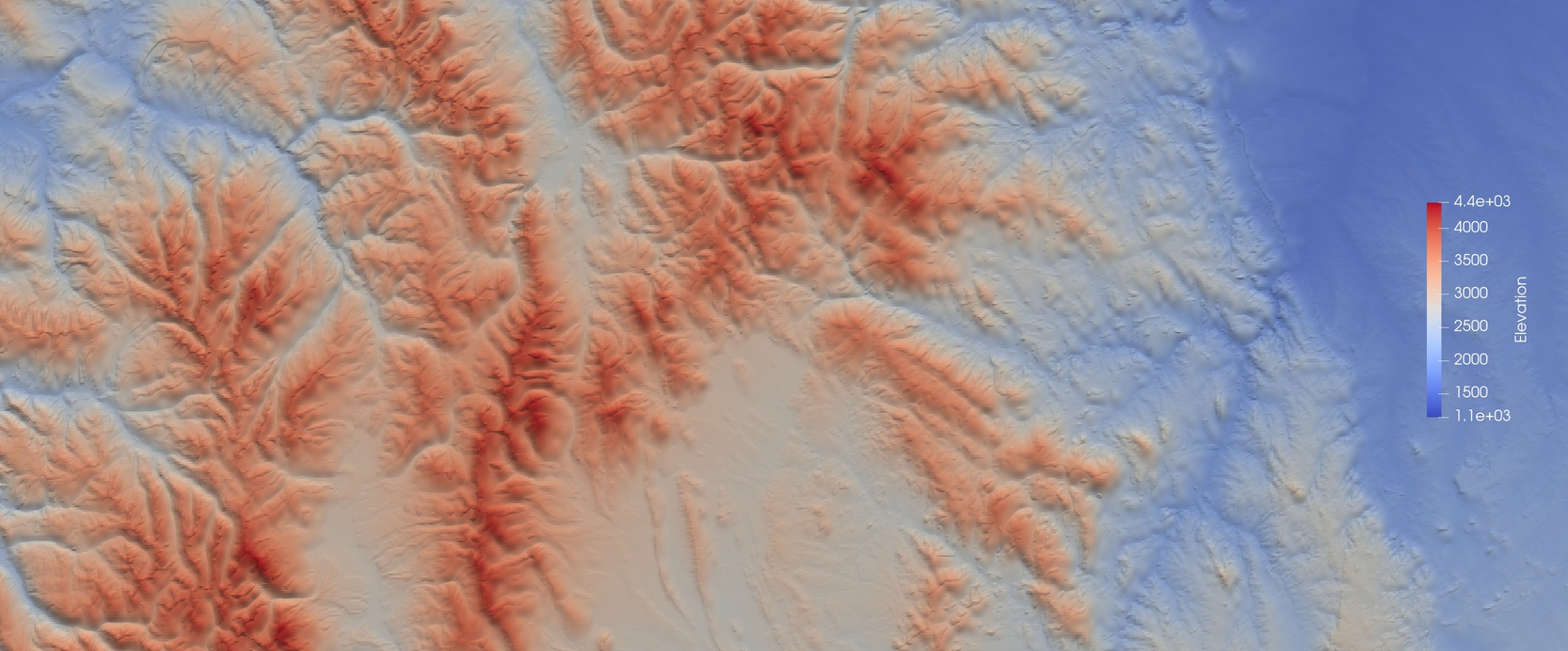
Fig. 9 Rocky Mountains Elevation Map SRTM data set
Using the SRTM Data for Domains Containing Ocean
Because it is not necessary to specify the elevation of the ocean surface,
the SRTM data set does not provide data over these areas. Normally
the terrain_mesh program would issue an error message and halt if an
elevation data file were missing, but this behavior can be modified by
passing the -o flag (i.e. terrain_mesh -o). In this case a missing
data file is assumed to be an ocean area and the elevation is simply set
to zero over this region.
Custom Data Set
The terrain_mesh program can handle a more broad collection of elevation data via the custom file option (i_data_type=2). Currently the elevation data must be contained in a single file named terrain.dat and this data must be sampled on a uniform mesh containing Nx_dat x Ny_dat data points in the latitude, longitude space. The terrain.dat file format is single-precision floating point binary with no control characters.
A sample input using the custom data type is shown below.
lat_ref      40.5000   Latitude  for point in domain
lon_ref     -105.875   Longitude for point in domain
lat_min_dat     40     Specifies corner of the domain for custom data type
lon_min_dat   -106     Specifies corner of the domain for custom data type
delt_lat_dat   1.4     Specifies size of the domain for custom data type
delt_lon_dat   1.4     Specifies size of the domain for custom data type
Nx_dat         100     Number of data points in x direction for custom data type
Ny_dat         100     Number of data points in y direction for custom data type
i_dat_type      2      Custom
z_edge         000     Average altitude of domain edge/altitude of ocean/...

data_path /your/path/to/custom/data
Terrain Damping
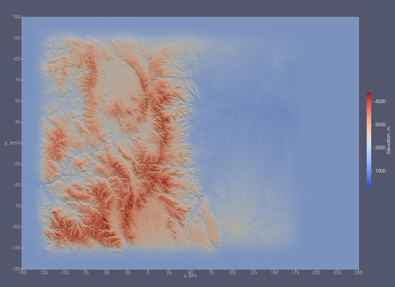
As previously mentioned, it is necessary to damp the terrain around the edges to avoid potential numerical error specifically when periodic boundary conditions are used in either the x or y directions. Special cases where the edge of the domain is already at constant elevation, namely, domains surrounded by ocean, can bypass this input. A sample input for the Rocky Mountain case (surface generated shown below)
lat_ref      40.0000   Latitude  for point in domain
lon_ref     -105.875   Longitude for point in domain
rot           -30      Rotation angle with respect to lines of constant latitude
n_fit:          1      Interpolation order 1, 2 or 3.
i_dat_type      1      Type of data files 0-GLOBE, 1-SRTM, 2-custom
width_x     5.000e+4   Width of the terrain damping function in x
width_y     5.000e+4   Width of the terrain damping function in y
x_damp0    -1.000e+5   Position of damping function at the left   x boundary
x_damp1     1.500e+5   Position of damping function at the right  x boundary
y_damp0    -1.000e+5   Position of damping function at the bottom y boundary
y_damp1     1.000e+5   Position of damping function at the top    y boundary
z_edge      1.500e+3   Altitude to set terrain around the damped edges

data_path /your/path/to/SRTM/data
For general cases it is not required to specify the starting location of the damping function (x_damp, y_damp) as the default will damp the width from the edge of the domain. To illustrate the properties of the hyperbolic tangent function used to damp the terrain, the following inputs were used.
width_x     5.000e+4   Width of the terrain damping function in  x
x_damp1     1.500e+5   Position of damping function at the right x boundary
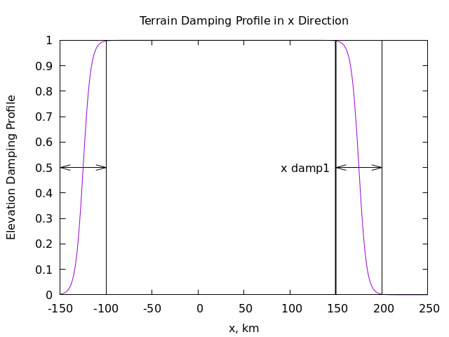
Fig. 10 The width_x is the distance of the region between no damping and fully damped illustrated by the arrows. Specifying the x_damp1 moves the beginning of the damping profile on the right hand side to the value supplied.
A fully rendered surface from the input above is shown
